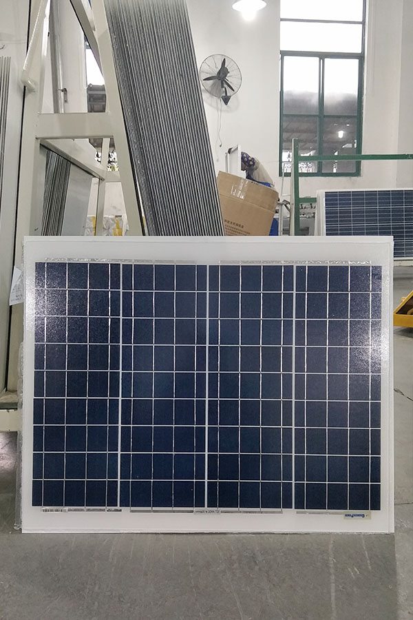
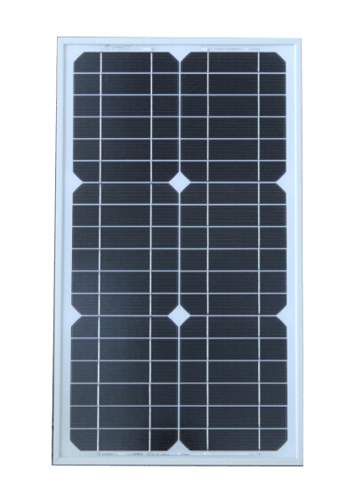
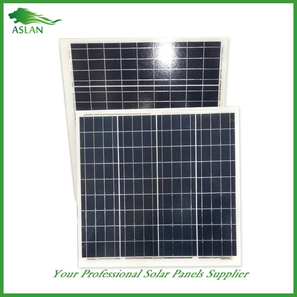
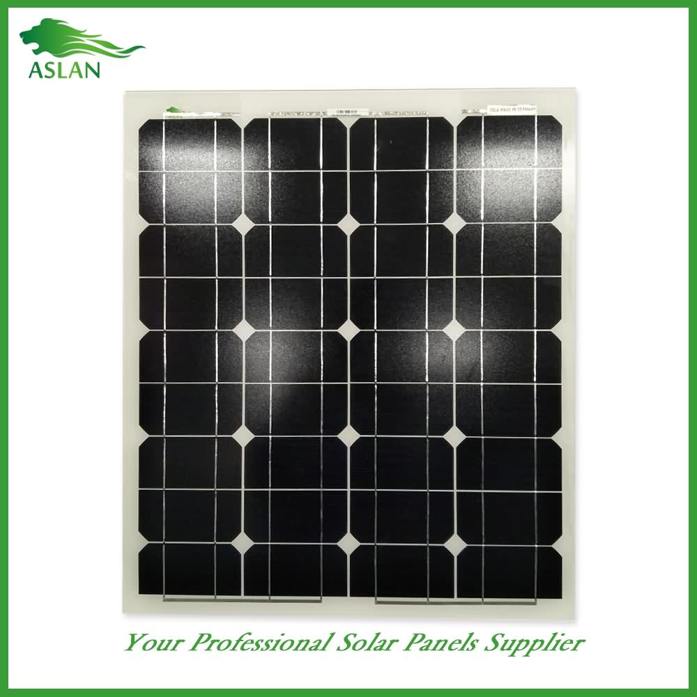
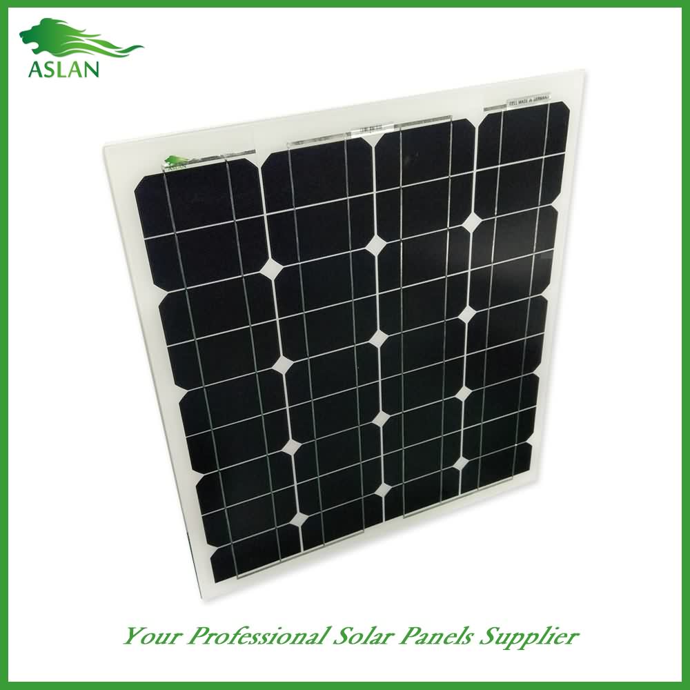
Wholesale Price China Mono-Crystalline 50W Solar Panel Supply to Jakarta
Short Description:
We always work as a tangible team to ensure that we can provide you with the best quality and the best price for Wholesale Price China Mono-Crystalline 50W Solar Panel Supply to Jakarta, welcomes all overseas friends and merchants to establish collaboration with us. We will provide you with honest, high quality and efficient service to meet your requirements.
Technical parameter
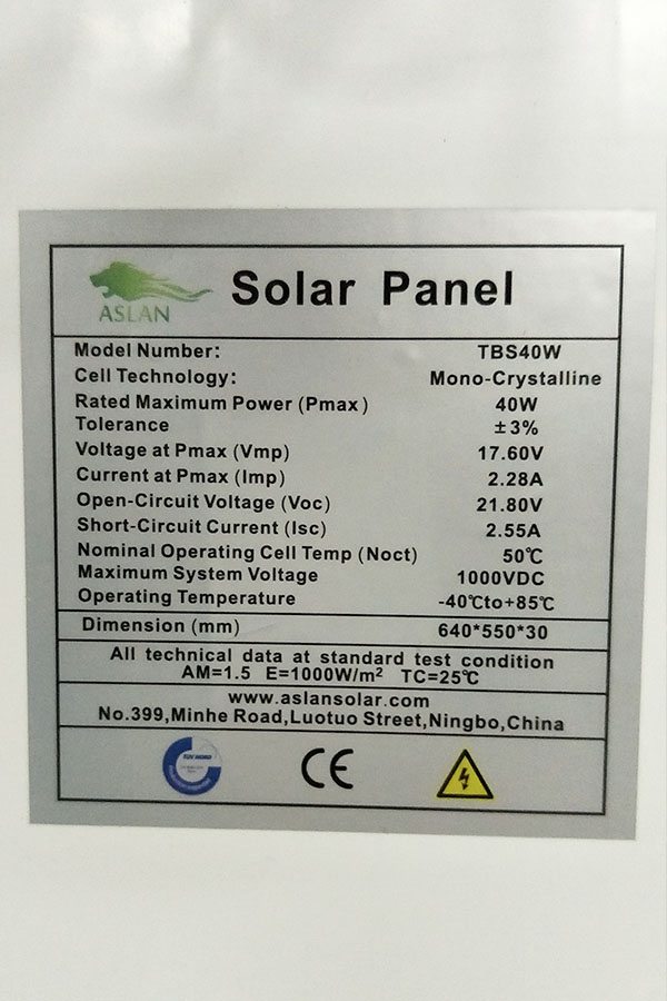
Maximum Power(W) 50W
Optimum Power Voltage(Vmp) 18.72V
Optimum Operating Current(Imp) 2.67A
Open Circuit Voltage(Voc) 22.83V
Short Circuit Current(Isc) 2.94A
Mechanical Characteristics
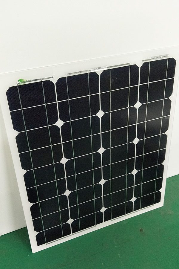
Cell Type Monocrystalline 125×62.5mm
No of Cell 36 (4x9pcs)
Dimensions 636x554x25mm
Weight 4.2Kg
Front Glass 3.5mm,High Transmission, Low Iron,Tempered Glass
Junction box IP65 Rated
Output Cable TUV 1×4.0mm2/UL12AWG,Length:900mm
Temperature and Coefficients
Operating Temperature(°C): -40°C ~ + 85°C
Maximum System Voltage: 600V(UL)/1000V(IEC) DC
Maximum Rated Current Series: 15A
Temperature Coefficients of Pmax: -0.47%
Temperature Coefficients of Voc: -0.389%
Temperature Coefficients of Isc: 0.057%
Nominal Operationg Cell Temperature (NOCT): 47+/-2°C
Materials of solar panel
1).Solar Cell——Mono-crystalline solar cell 125*125mm
2).Front Glass——-3.2mm, high transmission, low iron, tempered glass
3).EVA——-excellent anti-aging EVA
4).TPT——-TPT hot seal made of flame resistance
5).Frame——anodized aluminum profile
6).Junction Box——-IP65 rated, high quality, with diode protection
Superiority: high quality anodized aluminum frame, high efficiency long life, easy installation, strong wind resistance, strong hail resistance.
Features
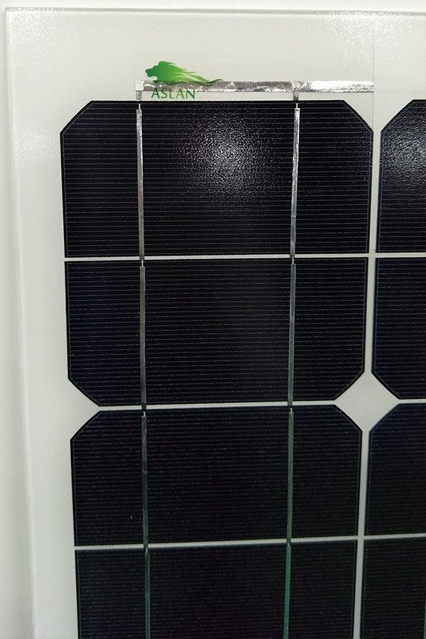
1. High cell efficiency with quality silicon materials for long term output stability
2. Strictly quality control ensure the stability and reliability, totally 23 QC procedures
3. High transmittance low iron tempered glass with enhanced stiffness and impact resistance
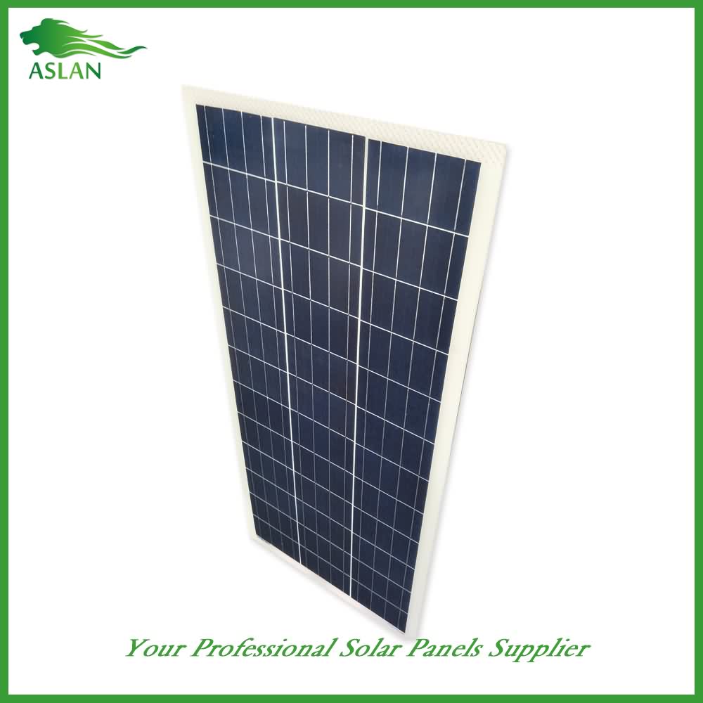
4. Both Poly-crystalline and Mono-crystalline
5. Excellent performance in harsh weather
6. Outstanding electrical performance under high temperature and low irradiance
Quality assurance testing
Thermal cycling test
Thermal shock test
Thermal/Freezing and high humidity cycling test
Electrical isolation test
Hail impact test
Mechanical, wind and twist loading test
Salt mist test
Light and water-exposure test
Moist carbon dioxide/sulphur dioxide
This is the last part of the mechanical build. In this video we complete the construction of the CNC Machine. Hope you enjoy it.
——————//——————
PCB Milling Machine Series: https://goo.gl/PA5Uly
Instructable: https://www.instructables.com/id/DIY-PCB-Milling-Machine-Part-3-X-and-Z-Axis/
——————//——————
FOLLOW ME ON:
http://instagram.com/mrjcrp
http://facebook.com/kalaakaar.in
http://twitter.com/mr_jcrp
——————//——————
MORE PROJECTS TUTORIALS and POSTS
http://www.mediamilan.com
——————//——————
MUSIC: Bit Quest (incompetech.com)
——————//——————
In Fusion360 I was able to model the exact dimension of the Y-Axis build plate. It has the linear bearing positions and where to drill holes. I printed them out in actual size on A4 and then stuck them together.
Now I can cut out just the piece that I need and use some paper glue to stick it to the MDF. This is 18mm MDF and after cutting this is the result. I am going to drill holes here to accept the linear bearings. On the top side of the MDF I am countersinking some holes to accept the head of the allen key. This would keep the surface flush.
Then mounting becomes straightforward by adding screws and nylock nuts. The smooth rods need to be parallel to each other for smooth Y-Axis motion. So I move the plate to each end and then tighten the screws.
The next would be motor and belt mounts. This houses the motor but first we will make the belt tensioner. This is the tensioning screw and the flange bearings. I bought these from Ebay and usually used with 3D printers. All the parts are printed with 5mm thickness so they are plenty strong. Now on this flange bearing the belt can rotate on and this screw will tension the belt.
To attach it to the frame I can use the T-Nuts I had already included in the first episode. The belt tensioner is attached to the front of the machine. This will allow easy access whenever we need. Adding the belt tensioner to the front meant that the motor mount goes at the back.
When I designed the X-Axis I did not know where I will attach the belt. So I designed this pieces separately. But now that all is setup I can measure and add this to the fusion model. So when you download you can find the matching holes in the model.
To hold it in place I added some super glue. Once it dries its strong enough. Still I chose to add some screws for extra strength.
I am eyeballing the placement of the motor. It has to be in line with the belt holder. Then I can screw the motor holder in place. And then mount the motor to it. Here I am attaching the 20 teeth Gt2 pulley. On the other side I can now attach the belt tensioner.
The GT2 belt I used was 6mm wide and had pitch of .2mm. This is a very common one used in most of the CNC’s that you buy from Banggood. Fixing it will be as simply as rolling it through the motor and belt tensioner and connecting it back to the belt holder using zip ties. It is necessary that while making the first loop I add it as tight as possible and without much slag. Only then a little bit of tensioning can make the belt strong.
After tensioning here I am manually moving the X-Axis to see if the belt stays within the pulley.
For the Y-Axis I made this small belt holder. Again while designing I did not know the position. But now after physical construction I can measure and add it to Fusion Model. So while downloading you can see markings for this piece in the design.
I can add the belt here too. Flipping the entire machine on its side helps in mounting this. GT2 belts are manufactured with some metal linings which makes them very strong for such purposes. The GT2 belt that I used on my 3D printer works fine till date.
With that mechanical build is all done. We have the X-Axis, Z-Axis and Y-Axis all done. Usually threaded rod is preferred when it comes to making a CNC. But I set out myself on a challenge to make the CNC with GT2 belt just to see how it works. And I can’t be more happier with my decision. All that remains is the adding the CNC shield, Arduino, GRBL and tweaking. Mostly electronics. So hopefully that will be last part of the series.
And to not miss the last part please subscribe to the channel. I am sure you will tons of questions which I would love to answer. Please drop them in the comments. If this video helped you learn something then please share it with your friends. Just by sharing you are helping me and this channel.
Until next time. Happy Learning.
WV300 FAIL
Vendor: Soled Energy – Milpitas, CA
Inverter FAILS to recover to full full power after a temporary shadow encounter such as a bird, plane, or cloud. (short version)