OEM Supplier for Poly-crystalline Solar Panel 2W for Holland
Short Description:
Our target is to consolidate and improve the quality and service of existing products, meanwhile constantly develop new products to meet different customers' demands for OEM Supplier for Poly-crystalline Solar Panel 2W for Holland, Inspired by the rapid developing market of the fast food and beverage consumables all over the world , We are looking forward to working with partners /clients to make success together .
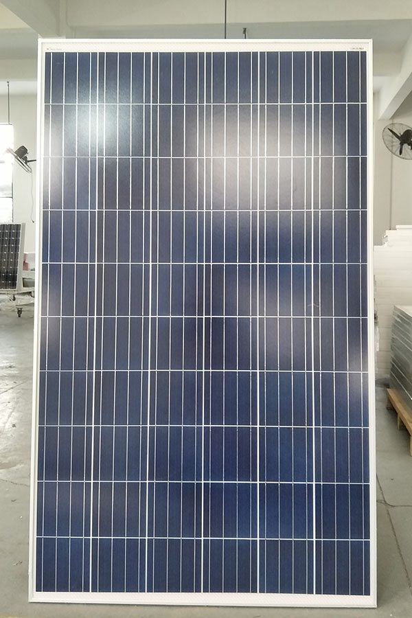
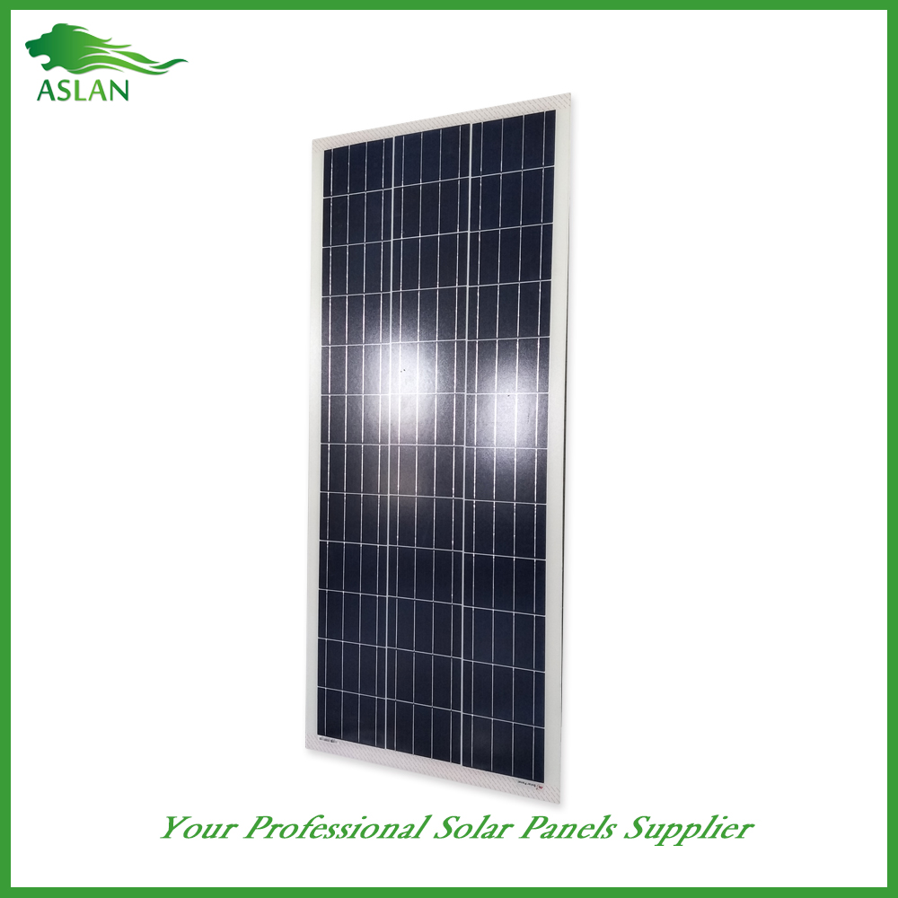
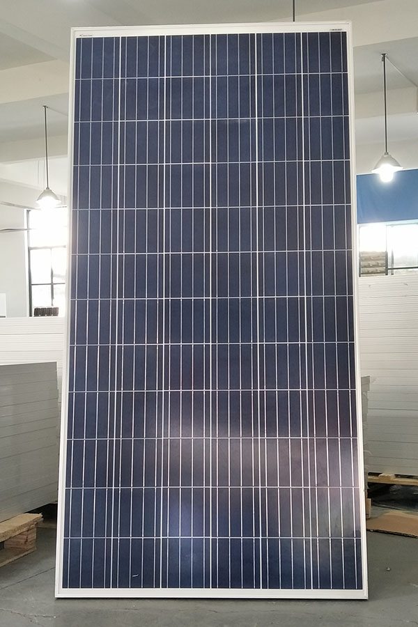
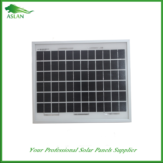
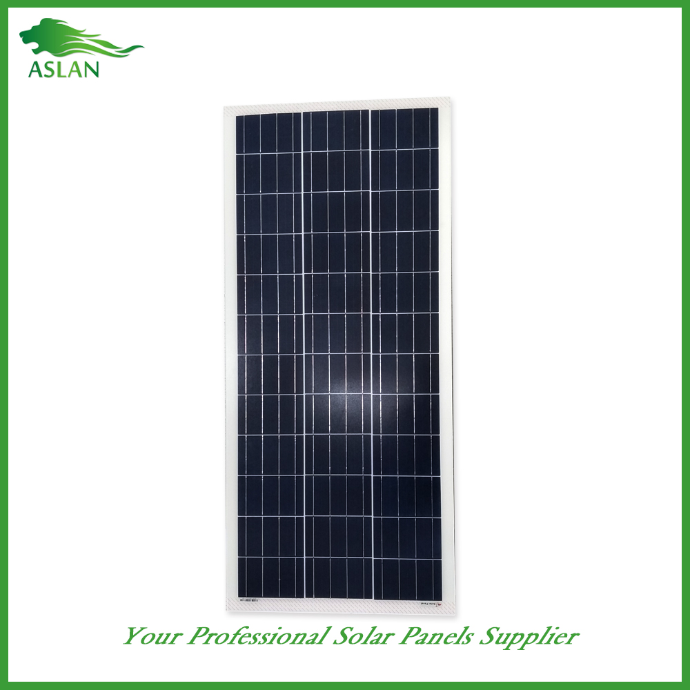
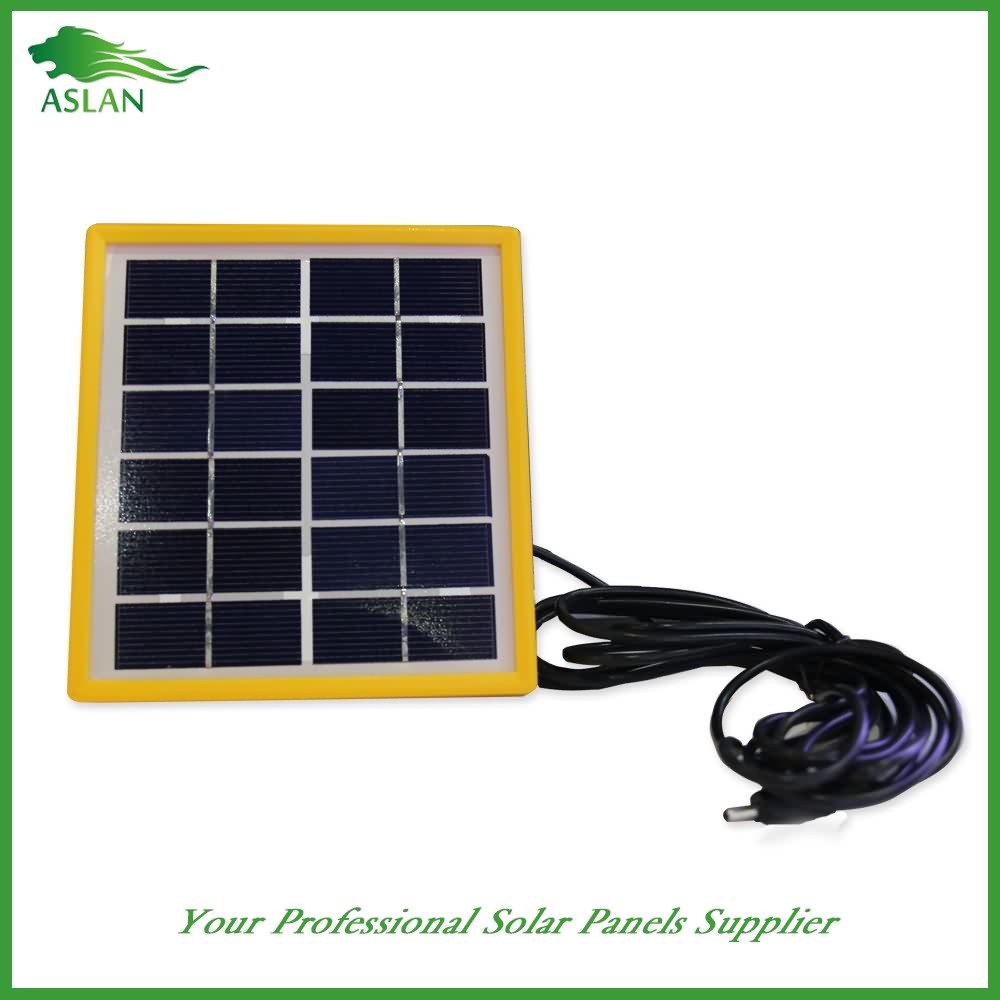
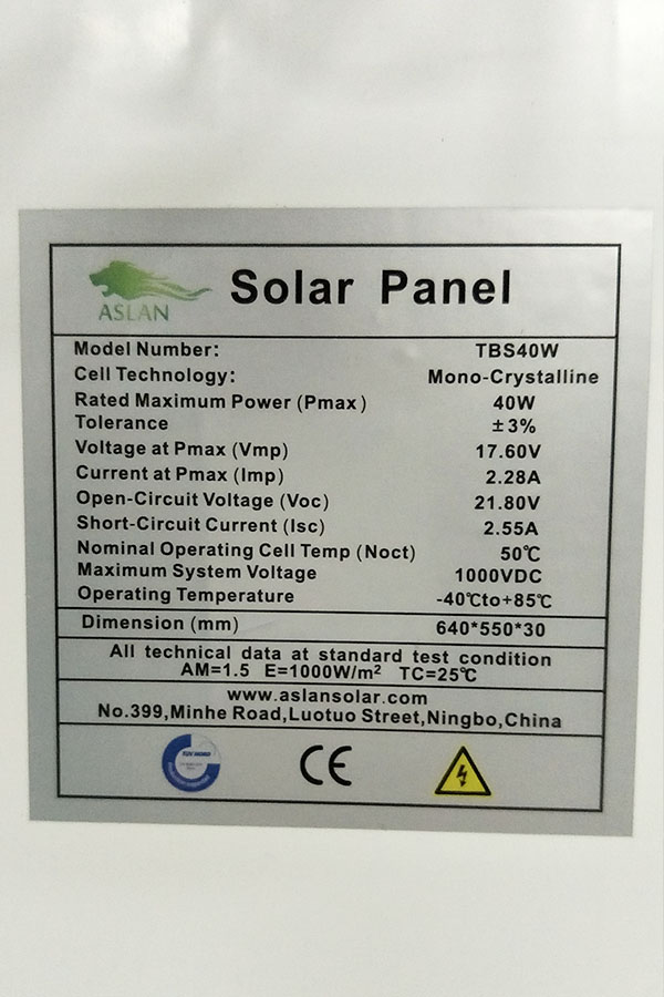
Poly-crystalline Solar Panel 2W
Technical parameter
Maximum Power(W) 2W
Optimum Power Voltage(Vmp) 6V
Optimum Operating Current(Imp) 0.34A
Open Circuit Voltage(Voc) 7.2V
Short Circuit Current(Isc) 0.37A
Mechanical Characteristics
Cell Type Polycrystalline
No of Cell 12 (2x6pcs)
Dimensions 145x145x18mm
Weight 0.4KGS
Front Glass 3.2mm, High Transmission, Low iron, tempered Glass
Temperature and Coefficients
Operating Temperature(°C): -40°C ~ + 85°C
Maximum System Voltage: 600V(UL)/1000V(IEC) DC
Maximum Rated Current Series: 10A
Temperature Coefficients of Pmax: -0.435%
Temperature Coefficients of Voc: -0.35%
Temperature Coefficients of Isc: 0.043%
Nominal Operating Cell Temperature (NOCT): 47+/-2°C
Materials of solar panel
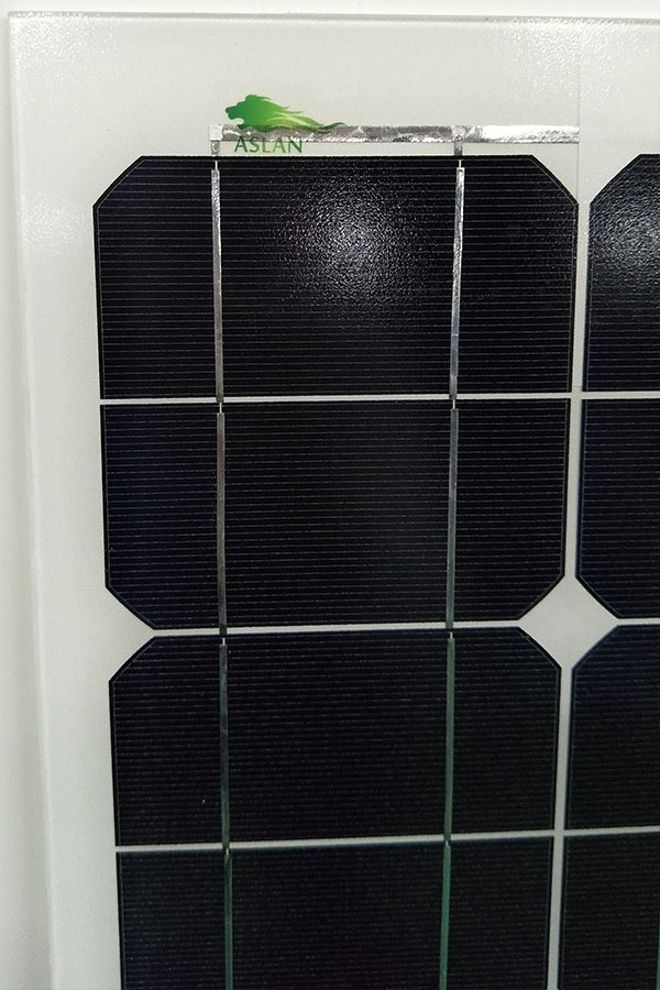
1).Solar Cell——Polycrystalline solar cell 156*156mm
2).Front Glass——-3.2mm, high transmission, low iron, tempered glass
3).EVA——-excellent anti-aging EVA
4).TPT——-TPT hot seal made of flame resistance
5).Frame——anodized aluminum profile
6).Junction Box——-IP65 rated, high quality, with diode protection
Superiority: high quality anodized aluminum frame, high efficiency long life, easy installation, strong wind resistance, strong hail resistance.
Features
1. High cell efficiency with quality silicon materials for long term output stability
2. Strictly quality control ensure the stability and reliability, totally 23 QC procedures
3. High transmittance low iron tempered glass with enhanced stiffness and impact resistance
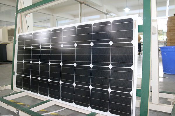
4. Both Poly-crystalline and Mono-crystalline
5. Excellent performance in harsh weather
6. Outstanding electrical performance under high temperature and low irradiance
Quality assurance testing
Thermal cycling test
Thermal shock test
Thermal/Freezing and high humidity cycling test
Electrical isolation test
Hail impact test
Mechanical, wind and twist loading test
Salt mist test
Light and water-exposure test
Moist carbon dioxide/sulphur dioxide
• Link of our Facebook page : https://www.facebook.com/DIY.Experiments.YouTube
• Text of the video :
Hi everyone, today we’ll show you how to make an inverter! An inverter provides power to objects working on alternating current with only a 12 V battery. First we’ll test our inverter on different devices then we’ll show you how to create yours.
Let’s start with a simple test. We plug the terminals on the 12 V battery and then we switch on the inverter. The bulb, which normally works on AC with 230V and consumes 25 Watt, is now on as if it was plugged in the power outlet! Instead of using high consumption light bulbs, we can use economic light bulbs, here is a test with 36W, and as you see it works perfectly. Here is another test with our inverter; we will recharge at the same time an iPod, an iPhone and an iPad. When we switch on, there is enough energy remaining to light up a bulb. The inverter is compatible with every switching-mode power supply, even the most powerful ones. Now we will try to supply a stereo. I turn up the volume gradually. So obviously we can’t reach the volume’s maximum because the inverter can give only up to approximately 30 Watt while the stereo reaches 260 Watt when on maximum volume. There is black out? With the inverter we can supply energy to your room’s lamp. The soldering iron’s cable is too small? With the inverter, the cables are never too small !
Our inverter is made out of 3 parts:
- We have a 50 Hz oscillator
- 2 MOSFET transistors that amplify the signals
- And a transformer
We first have to make the oscillator which can be considered as an integral component. The positive terminal is placed in the upper position, while the negative one is in the lower position. It consumes 30mA under a 12 V current. On the sides it supplies a positive current on one side and a zero current on the other side, and vice-versa, with the frequency that we wish. To have a 50 or 60 Hz frequency, the mains frequency, we will give the specifications of the capacitors and resistances that we used at the end of the video.
As for the transistors, we can consider it as an amplifier with 3 terminals: base collector and emitter. For the transistor that we are using, when there is a small current between the base and the transmitter, a much powerful current can flow between the collector and the emitter. For example, the current that flows through this resistance would have never been able to light the bulb, but thanks to the transistor, the signal that I’m doing can be reproduced in the bulb.
In our inverter we use MOSFET transistors. They act like the other transistors except that their terminals are named Gate (G), Drain (D) and Source (S). The current that must flow between G and S to activate D and S can be very low. As long as there is more than about 4V between G and S, the other circuit is activated. As you can see the current that can flow through the body is enough to activate the MOSFET transistor!
We use MOSFET transistor for our inverter because they need very low voltage between G and S to be activated which doesn’t affect the oscillator’s frequency. Since we use recycled components only, the MOSFETs even from different objects have relatively the same specifications, which is very important since the transistor have to be in perfect sync: there should be neither any dead time nor a time when both transistors are activated. We connect the two sides of the oscillator to the transistor’s G terminals. Since the frequency is 50 or 60Hz, each hundredth of a second the activated transistor changes.
The transformer must have a 1 to 19 ratio so we can go from 12 V to 230 V, twice less to reach 110V. Since the primary coils are in opposite directions, the direction in which the induced current in the secondary coil flows is opposed to the one from either one of the primary coils. We have a 230 V and 50 Hz current, not really sinusoidal but ideal for supplying mains powered devices.
Other tests:
A last test with 24 V, this way we can have an 85 Watt power tested here with 2 bulbs: a 60 Watt bulb and a 25 Watt bulb fully lit. However, with 24 V the voltage isn’t stable and we can only obtain 230 V when we consume 85 Watt, and less we consume more the voltage is increasing, it can go up to 600 V on open circuit.
We have to supply the circuit with 12 V which consumes 500 mA open and up to 7 A in short circuit with 230 V; this is why we use a big lead battery so that we can have a range of several hours. We have for example a range of 5 hours and a half with this 10 Watt bulb; we can also supply a 230 V laptop stereo with only two 9 V batteries, I switch it on and it works !
โซล่าเซลล์ ยี่ห้อ ฟรอนเทียร์ โซล่าเซลล์ไทยแลนด์ Solar Cell Thailand สินค้าราคาปราบเซียน รับติดตั้งทั่วไทยโทร .0813959408
ID LINE : Solarcell.thailand